Buzon’s U-TRAY: Incorporating a safety grate into the design of a deck built on pedestals

On a raised deck, the choice of decking material cannot be separated from the choice of its supports. Slab size, anticipated foot traffic, available height, and how specific areas are handled all influence the overall design. For architects, specifiers, and installation contractors, safety must be considered at the level of the entire system, not just an individual component.

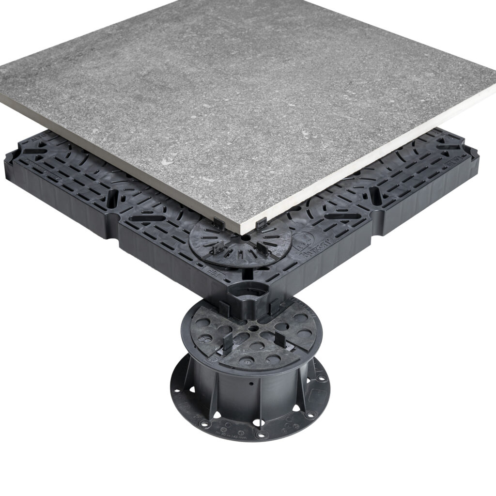
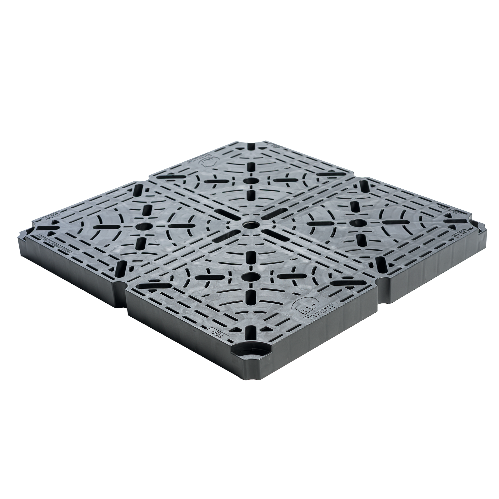
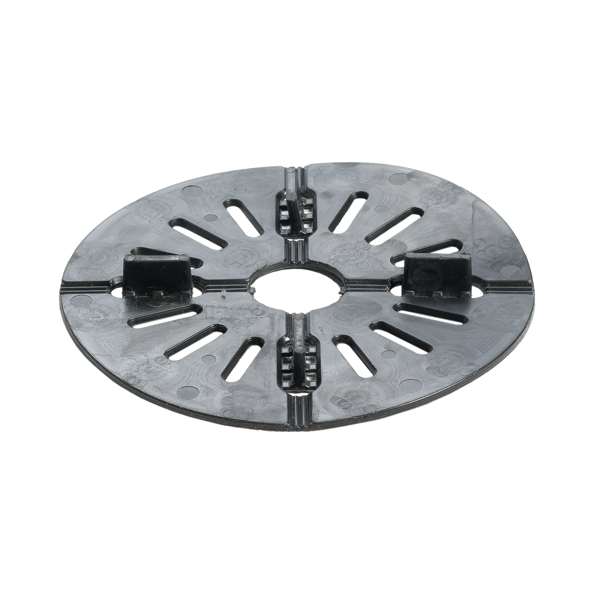
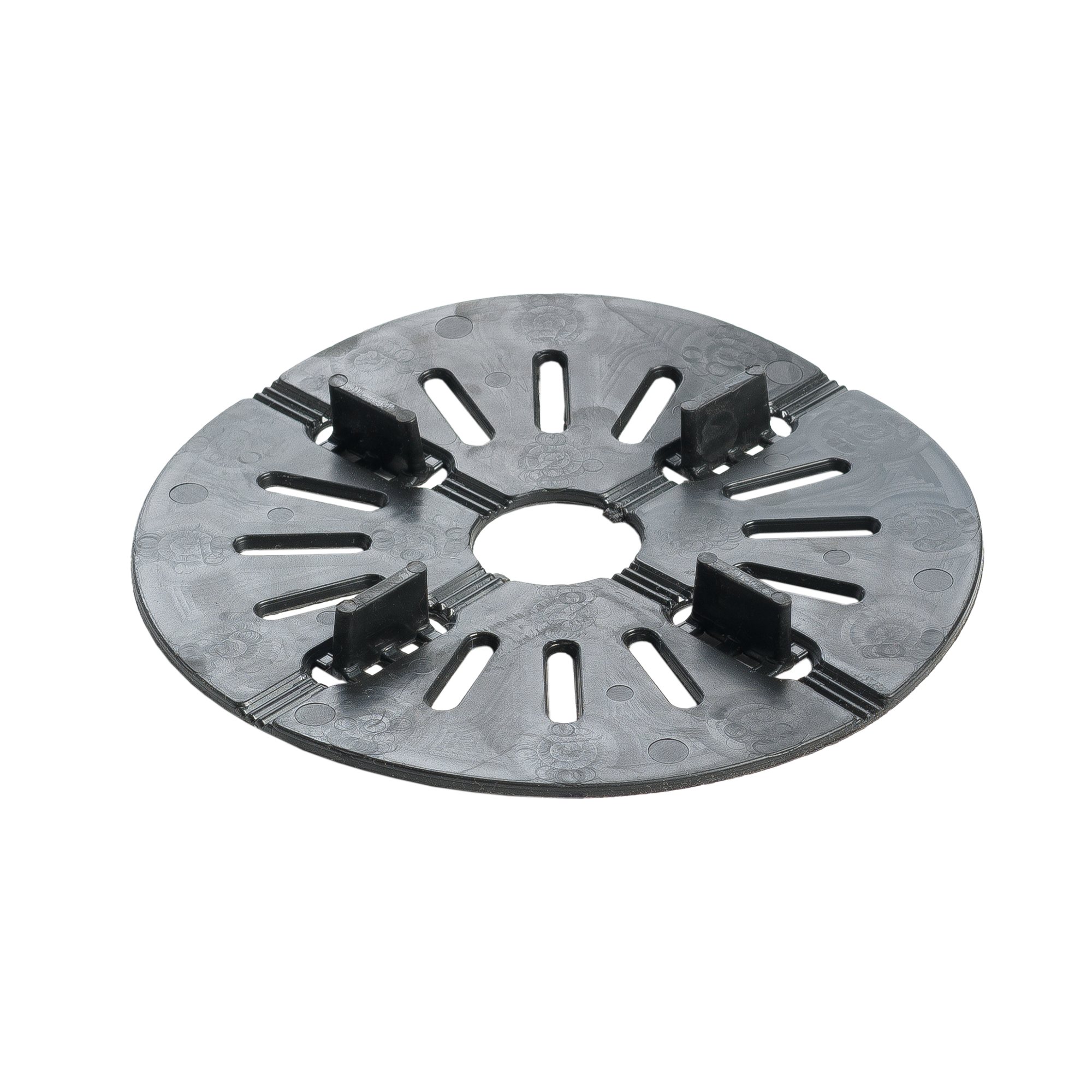
Buzon’s U-TRAY grid is installed beneath the flooring of a terrace supported by pedestals. It provides an additional support element beneath the slabs and can be designed to limit the consequences of accidental flooring failure, depending on the chosen configuration. However, its integration requires verification of component compatibility, loads, and the project’s installation specifications.

A safety grid beneath the surface finish

Made from recycled polypropylene, the U-TRAY is designed to sit between the pedestals and the terrace slabs. If a slab breaks, the grid may help reduce the risk of someone falling through the surface.

This function should not be interpreted as a guarantee against all accidents. Its effectiveness depends in particular on the type and size of the slabs, the grid layout, the number of supports and the expected loads. The U-TRAY does not replace proper design of the surface finish or verification of the terrace’s stability.

For professionals, it is therefore a component to consider at the specification stage, particularly where safety in use and the surface configuration require closer attention.

A modular format to coordinate with the layout plan

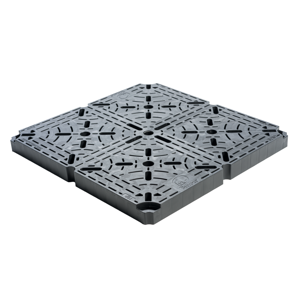
The U-TRAY grid has a square format of 496 × 496 mm. This dimension must be considered when planning the layout, alongside the slab dimensions and pedestal positions. The original article lists several slab sizes, including 60 × 60 cm, 120 × 60 cm, 120 × 30 cm, 90 × 45 cm, 120 × 40 cm and 90 × 90 cm.

This range of sizes does not mean that every combination can be installed in the same way. Before selecting a configuration, the required support points, cuts and edge details, and any additional measures specified by Buzon should be checked.

The system therefore allows different architectural finishes to be considered, provided the aesthetic choice remains compatible with the technical requirements of the surface finish.

Planning installation with pedestals and connectors

The grids are designed to be placed on fixed or adjustable Buzon pedestals, according to the configurations permitted for the project. Pedestal adjustment sets the terrace level, while the support layout must be determined according to the grids, slabs and loads.

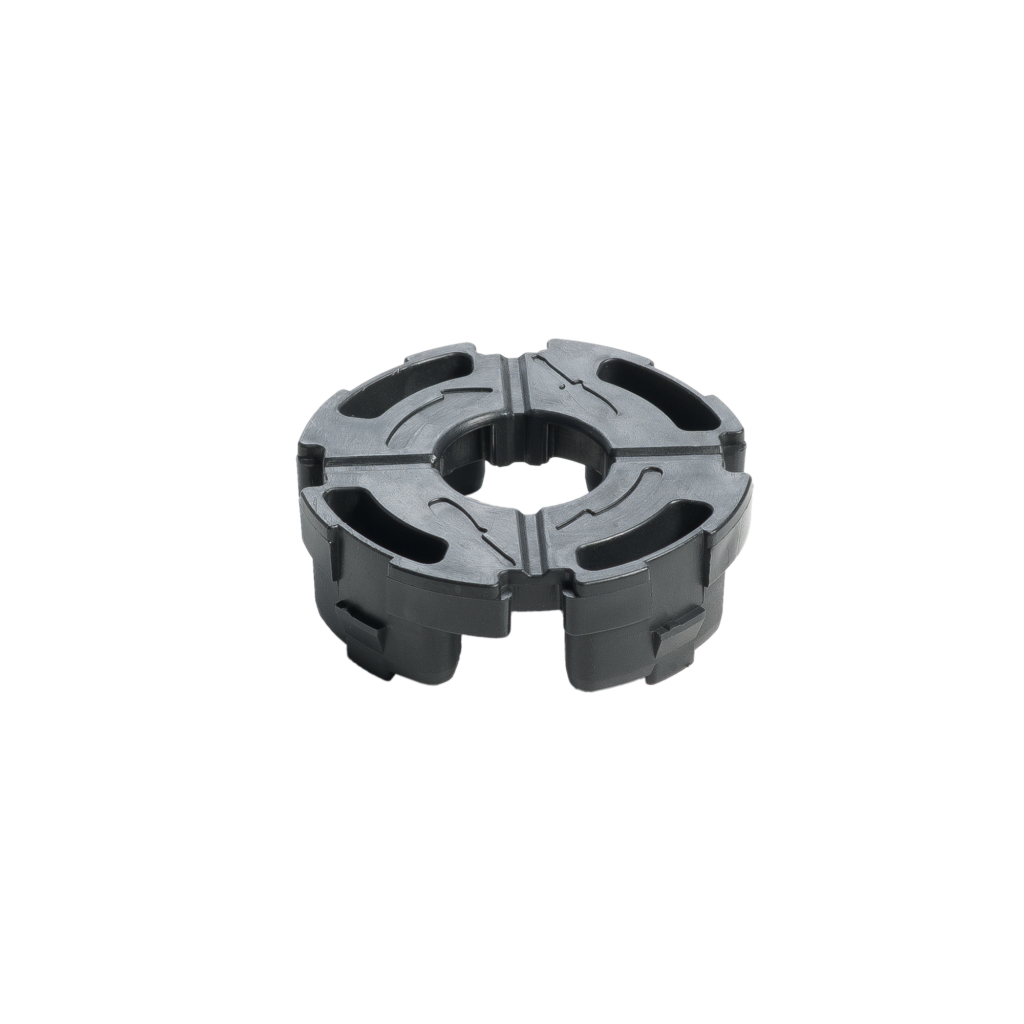
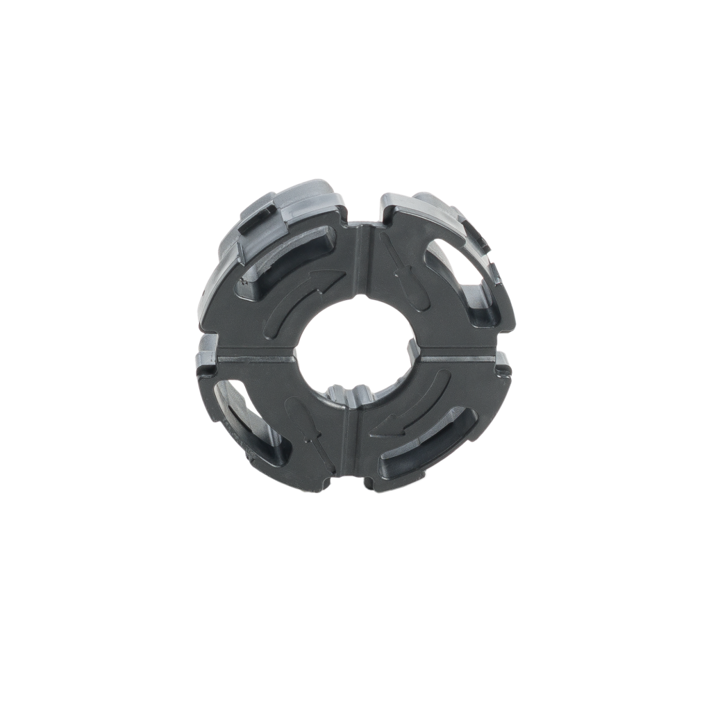
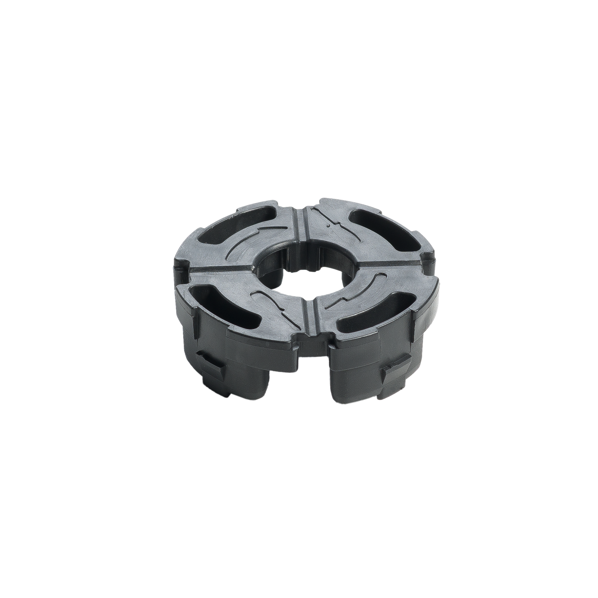
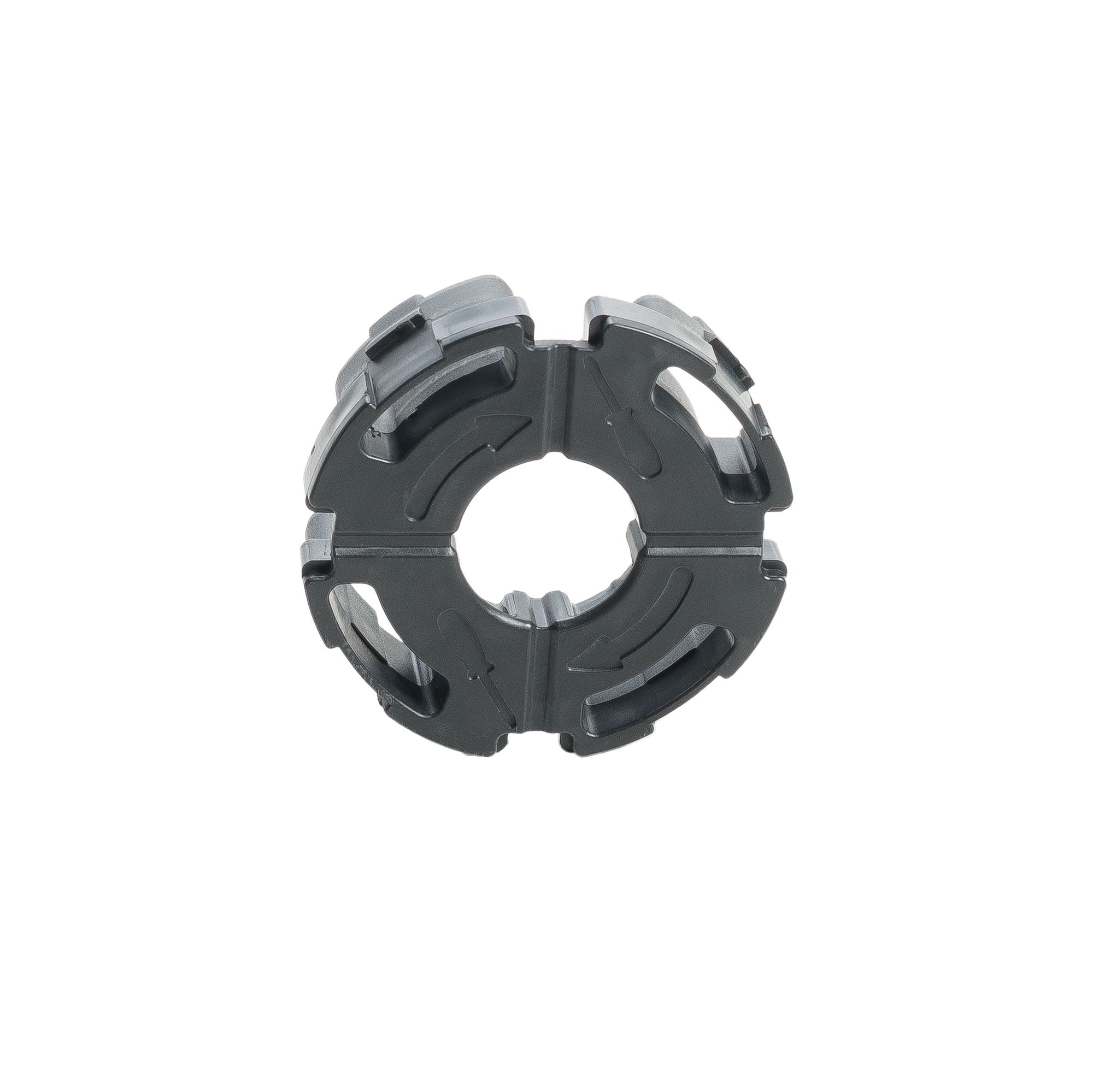
The rotating U-TRAY-LOCK connector joins four grids at their junction without tools for this assembly step. It helps form a continuous grid surface. The simplicity of this connection does not remove the need to check alignment, edges and overall stability before laying the surface finish.

Assessing the need for a central support

In some configurations, an additional central support may be considered beneath the grid. Whether one is needed, and where it should be positioned, must be determined according to the technical specifications for the selected assembly, rather than solely on the basis of heavy foot traffic.

U-TRAY-TABS for consistent joints between slabs

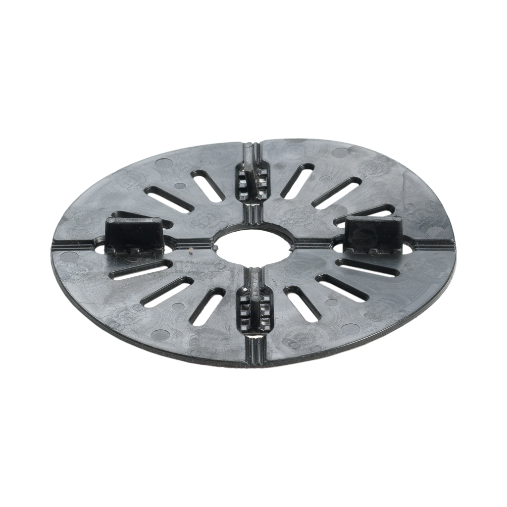
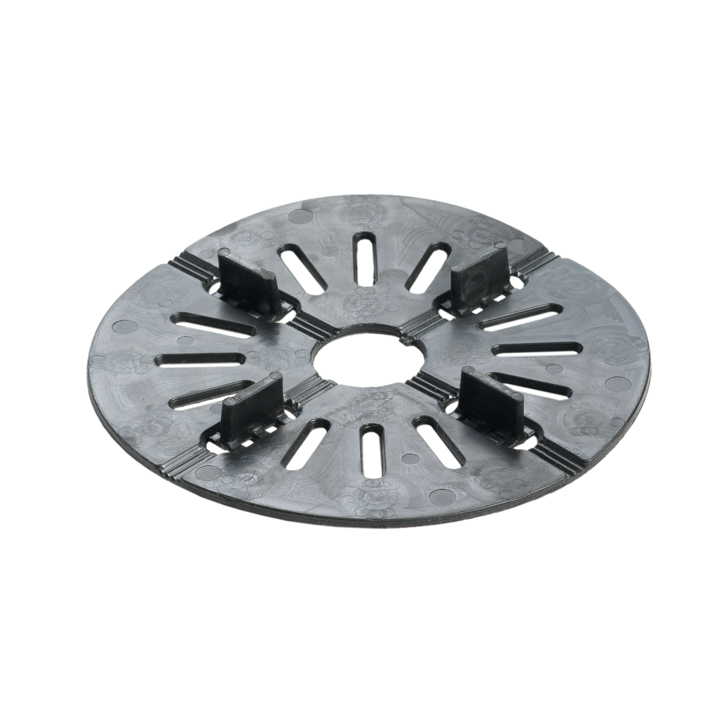
The U-TRAY-TABS complement the system when installing the slabs. These thermoplastic rubber discs have spacing tabs that create consistent joints of 2, 3 or 4 mm, depending on the selected model.

The specifications stated in the original article are a diameter of 130 mm, a height of 20 mm and a weight of 29 to 33 g. The tab thickness selected must suit the surface finish and the planned installation details.

The spacing tabs help align the slabs, but they cannot, on their own, correct an uneven level or incorrectly positioned supports. These adjustments must be made at pedestal level and checked during installation.

Which projects could use the system?

The U-TRAY can be considered for balconies, roof terraces, patios and other raised terraces. Each project has different constraints: imposed loads, installation height, exposure, water drainage, access to the waterproofing and edge details.

Before specifying the system, professionals should define in particular:

  • the surface finish and its dimensions;
  • the layout of the grids and pedestals, including any additional supports;
  • the loads and conditions of use;
  • edge, threshold and cut details;
  • the route taken by water beneath the surface finish;
  • inspection and maintenance arrangements, where required.

Designing for safety across the entire terrace

The U-TRAY adds a grid beneath the slabs and gives professionals another option when designing a pedestal terrace. Together with the U-TRAY-LOCK connectors and U-TRAY-TABS spacing tabs, it forms a system in which each component serves a specific installation purpose.

Its value depends on assessing the entire assembly—substrate, pedestals, grids and surface finish—for the project’s actual use. Safety does not depend on the presence of the U-TRAY alone, but on the compatibility and design of the entire terrace.